Finite Element Analysis (FEA) is a numerical simulation technique used in mechanical engineering to analyze and predict the behavior of structures, components, and materials under various conditions such as: external forces, heat, vibration, and other physical effects. It breaks down complex geometries into smaller elements (finite elements) and solves governing equations for each element, providing highly accurate results. FEA is integral to the design, optimization, and validation of mechanical systems, offering significant benefits in structural integrity, thermal performance, fluid interactions, and overall system efficiency.
FEA has revolutionized mechanical engineering design that enhances reliability, efficiency, and safety while reducing costs and development time. As computing power advances, FEA continues to evolve, offering more accurate and faster simulations for engineering challenges.
-
Fundamentals of Finite Element Analysis
FEA works by discretizing a continuous structure into a mesh of small elements (triangles, quadrilaterals, tetrahedra, hexahedra, etc.). These elements are interconnected at nodes, and mathematical equations define their behavior under external influences.
The key steps in FEA include:
-
Preprocessing:
- Defining the geometry of the component.
- Creating a finite element mesh (higher resolution leads to more accuracy but increases computational load).
- Assigning material properties (elasticity, density, thermal conductivity, etc.).
- Applying boundary conditions (forces, constraints, thermal loads).
-
Solving:
- The system of equations is solved using numerical techniques like the Newton-Raphson method, Gaussian elimination, or iterative solvers.
- Results include stress, strain, displacement, and other relevant factors.
-
Postprocessing:
- Visualization of results via contour plots, deformation plots, and stress distribution.
- Interpretation of data for design improvements.
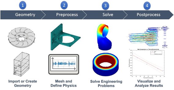
Image source: ww2.mathworks.cn
-
Key Roles of FEA in Mechanical Engineering Design:
- Structural Analysis
- Thermal Analysis
- Dynamic Analysis
- Fluid-Structure Interaction (FSI)
- Optimization and Material Efficiency
- Failure Analysis and Safety Assurance
Let’s take a deep look at each one:
1. Structural Analysis: helps engineers analyze the structural performance of components under various load conditions, such as tension, compression, bending, and shear. This includes-
- Static Analysis: Determines deformation and stress in a stationary system.
- Deformation Prediction: Identifies how much a structure will deform under various forces, ensuring it meets design specifications.
- Stress and Strain Analysis: Engineers use FEA to determine stress distribution in components under load, helping prevent failure.
- Dynamic Analysis: Evaluates the effects of time-dependent loads, including vibrations, impacts, and oscillations.
- Fatigue Analysis: Predicts failure over repeated loading cycles, ensuring longevity and fatigue life in mechanical components.
- Fracture Mechanics: Analyzes crack propagation and stress concentration points and failure points of materials subjected to cyclic loading.

Image source: giphy.com
2. Thermal Analysis: Thermal effects influence mechanical performance, and FEA provides insights into heat transfer and temperature distribution. This includes-
- Steady-State Heat Transfer: Identifies how heat distributes in materials and structures under equilibrium conditions.
- Transient Heat Transfer: Analyzes time-dependent thermal behavior, essential for systems like engines and cooling devices.
- Thermal Expansion Analysis: Evaluates thermal stresses due to expansion/contraction, preventing structural failure. Predicts material expansion and contraction due to temperature changes, avoiding thermal stresses.
- Optimization of Cooling Systems: Helps design effective heat dissipation methods in engines, electronics, and industrial equipment.
3. Dynamic and Vibration Analysis: Mechanical components often experience vibrations that can lead to fatigue or failure. This consists-
- Modal Analysis: Assesses natural frequencies to prevent resonance and mechanical failure.
- Harmonic Analysis: Studies response to periodic forces, such as rotating machinery.
- Transient Dynamic Analysis: Examines structures subjected to time-dependent forces like shocks and impacts.
- Impact and Crash Simulation: Helps in designing safer vehicles and protective structures.
- Seismic Analysis: Ensures buildings, bridges, and other infrastructure can withstand earthquakes.
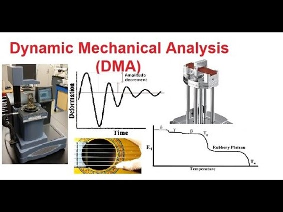
Image source: indiamart.com
4. Fluid-Structure Interaction (FSI): FEA is combined with Computational Fluid Dynamics (CFD) to study the impact of fluid forces on solid structures, crucial for aerodynamics, hydrodynamics, and biomedical applications.
- Aerospace Engineering: Studies aerodynamic forces on wings and fuselages.
- Automotive Engineering: Improves vehicle aerodynamics and cooling system performance.
- Biomedical Engineering: Analyzes blood flow interaction with medical implants (stents, artificial valves).

Image source: enteknograte.com
5. Electromagnetic and Multi-Physics Analysis: Used for components like electric motors, transformers, and PCB thermal management.
- Multi-physics simulations combine mechanical, thermal, and electromagnetic effects for complex system analysis.
6. Failure Analysis and Safety Assurance:
- Predicts Weak Points: Avoids catastrophic failures in mechanical components.
- Safety Standards Compliance: Ensures designs meet industry regulations (e.g., ASME, ISO, ASTM).
Applications of FEA in Mechanical Engineering
- Automotive: Crash testing, chassis optimization, thermal management.
- Aerospace: Structural integrity of aircraft, aerodynamics, vibration analysis.
- Manufacturing: Tool and die analysis, material forming processes.
- Biomedical: Prosthetics, implants, biomechanics.
- Energy Sector: Wind turbine blade analysis, thermal performance in power plants.
Benefits of FEA in Mechanical Design
1. Design Optimization
- Minimizes weight and material costs while maintaining strength.
- Allows engineers to explore multiple design configurations without physical prototypes.
2. Increased Reliability and Safety
- Identifies potential failure points before production, reducing risks.
- Ensures compliance with industry standards (e.g., ASME, ISO, ASTM).
3. Faster Product Development
- Reduces the need for physical testing, saving time and resources.
- Allows quick iterations of designs, shortening the design-to-production cycle.

Image source: gurov.com.au
4. Cost and Time Reduction
- Prototyping Reduction: Minimizes the need for physical prototypes, saving costs and development time.
- Early Design Validation: Identifies potential design flaws before manufacturing, reducing recalls and warranty claims. Detects problems early in the design phase, reducing manufacturing and warranty costs. Optimizes material selection and distribution, leading to cost-efficient production.
Future Trends in FEA for Mechanical Engineering
FEA is continually evolving with advancements in computing power and AI:
1.AI and Machine Learning in FEA
- Neural networks are being used to accelerate simulations.
- Predictive modeling helps in faster design iterations.
2. Cloud-Based FEA
- Cloud computing allows remote simulations on high-performance clusters.
- Reduces dependency on expensive in-house computing resources.
3. Real-Time FEA
- Integration with Digital Twins for real-time monitoring of mechanical systems.
- Used in predictive maintenance and failure prevention.
4. Advanced Material Simulations
- Nanomaterials and composites are being modeled with greater accuracy.
- Incorporating biomechanics for prosthetics and implants.

Image source: embs.org
-
Challenges and Limitations of FEA
While FEA is a powerful tool, it has certain limitations:
1.Computational Intensity
- Complex models require high processing power and memory.
- High-fidelity simulations can take hours to days to solve.
2. Accuracy Dependence
- Results depend on mesh quality and element selection.
- Poorly defined boundary conditions lead to inaccurate predictions.
3. Expertise Required
- Engineers must understand material properties, boundary conditions, and numerical methods to interpret results correctly.
- Misinterpretation can lead to design flaws and incorrect conclusions.
Conclusion
Beside these few limitations, Finite Element Analysis is a cornerstone of mechanical engineering design, offering powerful insights into structural, thermal, dynamic, and fluid interactions. It enables engineers to optimize designs, reduce costs, and ensure safety, driving innovation in various industries. As computational capabilities advance, FEA will continue to evolve, offering faster, more accurate, and real-time engineering solutions.
Join Us
Our aim is Prevention First! We strive to prioritize preventative measures over-reactive solutions. We believe in equipping our students with the knowledge and tools to maintain a safe and healthy work environment, which can prevent accidents or health issues from occurring in the first place.
Join Ken Institute and unlock a world of online courses in Occupational Health and Safety, Fire Safety, Environment and Sustainability and Mechanical Engineering. Propel your career to new heights.
Get in touch with us at: info@keninstitute.com
Visit our website: www.keninstitute.com
Call us on +917569034271
Let’s connect together on: Facebook, YouTube, LinkedIn, and Instagram.